Path > Steel (Assembly Unit)
Overview of Functions
Create a steel part that follows the path.
Path> Steel / Structure is created by extruding section or lofting different profiles. Based on the following rules, It will limit the direction of section and direction for structure generation.
Profiles of the structure can only be created in a plane normal to the master line.
Path of structure generation is always parallel to the master line.
These constraints are applied because they are dynamically updated based on the layout that the library are assigned. Geometry and the length needs to be automatically extended / reduced.
- EX) Girder of bridge
Details of Funtions
Create Tab > 1st sub tab
On/Off Option

Sets whether a cross section member is created. Set whether to use the User Section.
Define profile plane
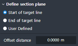
Define the plane on which to create the profile.
Start of target line : Towards the end point by the offset value inputted from the start point of master line. In the separated position, define the plane normal to the master line as the profile plane.
End of target line : Towards start direction by the offset value inputted from the end point of master line. In the separated position, define the plane normal to the master line as the profile plane.
User defined : At the position on the master line corresponding to the inputted ratio value, Define normal plane as the profile plane.
Distance from start profile plane* : Distance inputted from the plane of the Start profile at the distance from the value, you define the plane that is normal to the master line as the profile plane.
Displayed when Use User Section is ON
User section list
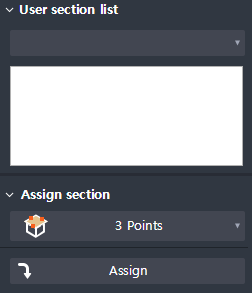
Section shape is created by inserting the registered User Section.
3 points : You can insert General Profile through 3 point click (origin, X axis of profile, Y axis of profile) at the click of a button.
Path> Concrete: Only User Sections with Material type 'Concrete' appear in the list.
Path> Steel: Only User Sections with Material type 'Steel' will appear in the list.
Generate member
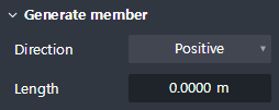
Displayed when Tapered Member is OFF
Set the Section’s direction of extraction and input its distance of extraction.
Direction : Sets the extraction direction of the profile.
Length : Enter the extraction distance of the profile.
Create Tab > 2nd sub tab
Cardinal point
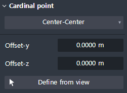
Sets the center-line position of the member.
Cardinal point : Sets the center line position based on the Bounding box of the profile.
Offset-y : Input the additional distance from the recently set , present Cardinal point to the direction of the Local-y axis of the profile.
Offset-z : Input the additional distance from the recently set, present Cardinal point to the direction of the Local-z axis of the profile.
Define from view : When clicking on the button, you can set the Cardinal point by clicking anywhere on the profile plan.
Create Tab > 3rd sub tab
Auto matching rule

Set the automatic vertex matching method between start section and end section.
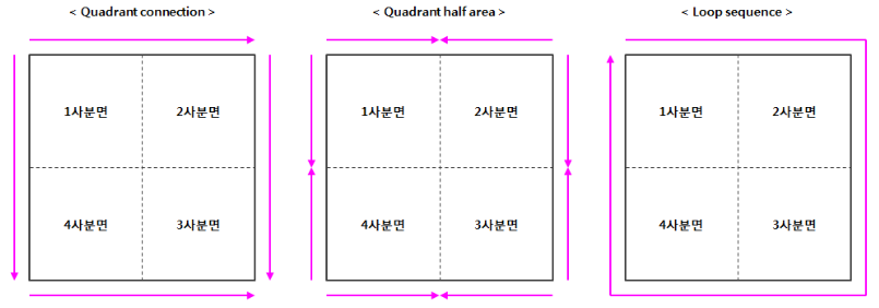
Quadrant connection : After matching the reference, vertices of each quadrant, vertices are sequentially matched according to the Loop Sequence of the profile in the direction of 'up → down' and 'left → right'.
Quadrant half area : After matching the reference vertices of each quadrant, vertices are sequentially matched within each quadrant, according to the Loop Sequence of the profile.
Loop sequence : After matching the reference vertices of the first quadrant , match the vertices sequentially according to the Loop Sequence of the profile.
However, if the number of vertices of start and end profiles does not match, quadrant half area method is automatically applied.
Since the three methods mentioned above are automatic matching methods based on program rules, the desired vertex matching results that the user might have pursued is not guaranteed.
Therefore, if it is possible to match the number of vertices in the Start profile and End profile through CAD work, then the Loop Sequence Method is recommendable.
Rotate quadrant of end profile
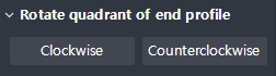
Rotates the End profile of the Quadrant order.
(Only if the auto matching rule is Quadrant connection, Quadrant half area it appears.)
Clockwise : Rotates the Quadrant order of the End profile clockwise.
Counterclockwise : Rotates the quadrant order of the end profile counterclockwise.
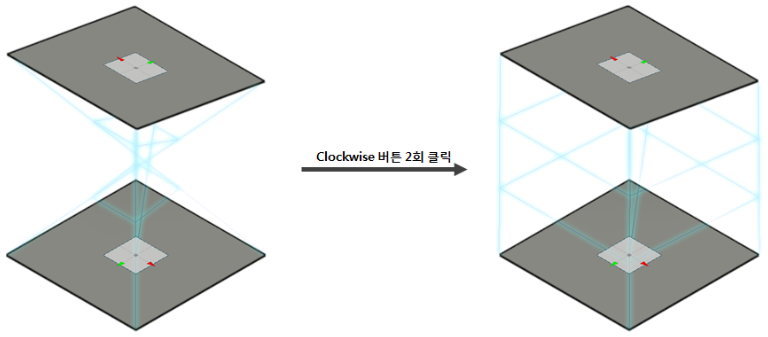
The quadrants of the Start and End profiles may be ordered differently than expected by the user's internal rules or the behavior of the General Profile.
The Rotate quadrant of end profile allows you to adjust the order of the quadrants in these situations.
Create Tab > 4th sub tab
Define shape variation
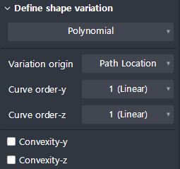
Defines the connection geometry between matched Vertices.
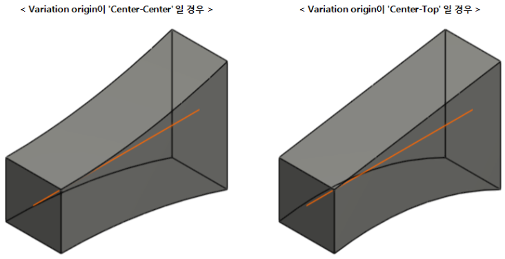
Variation origin : Set the reference point on the profile to determine whether the curve can be connected.
Vertex Sets that have the same distance from the Variation origin are always connected in a straight line regardless of the settings of the Shape variation.
For example, the figure below shows a part created by setting Variation origin differently and Curve order to '2 (Parabolic)' for the same profile. Looking at the connection shape of the upper vertex of the start / end profile, the left member has a different distance from the center-center, so the curved connection is applied, and the right member has the same distance from the center-top (0). You can see that a straight line connection is applied regardless.
(Polynomial)
Curve order-y : Sets the order of the curve with respect to the local y-axis direction.
Curve order-z : Sets the order of the curve with respect to the local z axis direction.
(Arc)
Radius-y : Enter the radius of the curve for y-axis direction.
Radius-z : Enter the radius of the curve for the local z-axis direction.
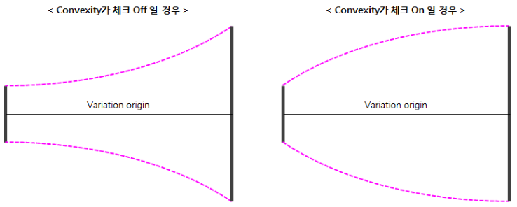
Convexity-y : Check if applying curve that changes convexly about Local y-axis direction.
Convexity-z : Check if applying curve that changes convexly about Local z-axis direction.
The rules for applying concave or convex curved shapes are shown below.
- Concave : Tangential curve shape is applied at the location of the vertex near the distance from the Variation origin.
- Convex : Tangential curve shape is applied at the position of Vertex which is far from Variation origin.
Option

When checked on, it maintains the extrusion rate of the 'Shape variation' line according to the change of the length of the object.
Property Tab > 1st sub tab
Classification
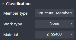
This is the function to set the properties of Path> Steel.
Object type : Indicates the type of object.
Member type : ou can select the type of member.
Work type : You can select the type of work.
Material : You can choose the material.
Group

Select a structure group.
Property Tab > 2nd sub tab
Element type
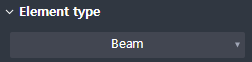
This is the function to set the 1D element type.
Four types are available.
Beam / Truss / Tension only / Compression only
Boundary condition
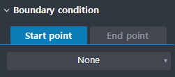
This is the function to set the boundary condition at the beginning and end of the geometry.
Constraint Tab
Section alignment
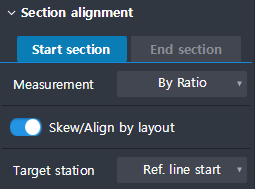
-