Tendon
Overview of Functions
The function models Tendons for selected members.
Defines group information regarding Tendons for the Tendon profile and defines the Reference axis for defining the reference coordinate system of the tendon profile.
Define the profile of the longitudinal and transverse tendons and the properties of the Anchorage.
Modeling of Tendons must be preceded by defining the Tendon group that manages the Tendon profile and the reference axis information that is the basis for the profile coordinates. (Step 1)
After the process above is defined, we provide the process of defining Tendon profile (Step 2).
Details of Functions
Setting Tab (Step 1)
Group
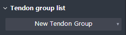
Define a New Tendon Group or import an existing Tendon Group that was defined previously.
Input / modify the name of the Tendon group.
Select target member
Select the target member(s) to place the Tendon.
Define path
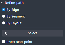
Select the Path for the direction of the longitudinal Tendon (y-axis Reference).
Selecting multiple Paths allows you to define a tendon profile only if the selected paths are consecutive.
By Edge : Specify the Selected Edge as the path.
By Segment : Specifies the Segment of the Alignment Layout as the path.
By Layout : Specify the Alignment Layout as the path.
Invert start point : When checked On, the starting point of the selected Path or the Tendon coordinates displayed at the end point. The position is reversed to the opposite.
X-direction of section
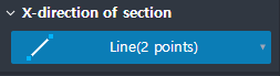
Define a New Tendon Group or import an existing Tendon Group that was defined previously.
Create & Edit Tab (Step 2)
Tendon type
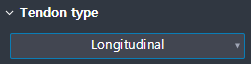
Select the type of Tendon Profile (Longitudinal / Transverse).
Tendon list
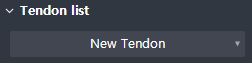
Define a New Tendon Group or import an existing Tendon Group that was defined previously.
Input / modify the name of the Tendon group.
Classification
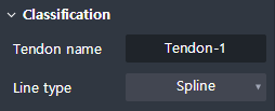
Set the properties of the tendon profile.
Tendon name : Set the name of the tendon.
Line type : Set the tendon linear type.
- Spline : Calculates and places the curve with the smallest curvature among the curves connecting points defining the placement of the Tendon.
- Round : Places the Tendon along a circle tangent to the lines connecting the points that define the placement of Tendons.
- Polygonal : Positions the Tendons by connecting points that define the Tendon's placement in a straight line.
Import profile
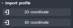
Displayed when Type > Longitudinal
This is convenient for inputting several tendon coordinates in one tendon group.
Excel can be pasted on and the format is shown below. If the input format is not valid, you cannot input it.
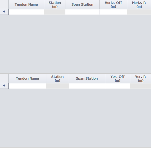
2D coordinate
- Station : Input the absolute position value with respect to the total length of the selected Path.
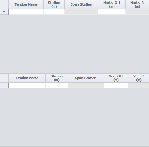
- Span Station : If Span is defined in the selected Path (Aligned Layout), this inputs the proportional position value of each Span (example: Span station: 2.5 means the middle position (0.5) of the second span (2.0).) If Span is not defined in the selected Path, the starting point ratio position of the path is 1.0 end point ratio position is 2.0, and only values between 1.0 and 2.0 can be inputted.
3D coordinate
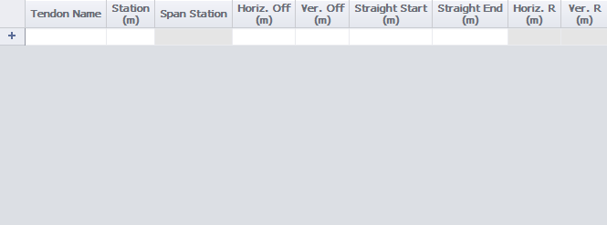
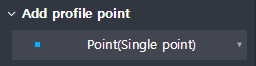
Add profile point
In the plan view or side view of the activated Tendon Editor Table, click on the point that defines the placement of the Tendon.
Offset profile
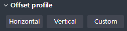
This is convenient for inputting the coordinate of profiles that are symmetrical in the vertical or horizontal direction with respect to the Reference point.
Horizontal : This batch reverses the Horizontal coordinates of the coordinates that were inputted in the Tendon profile table.
Vertical : This batch reverses the Vertical coordinates of the coordinates that were inputted in the Tendon profile table.
Custom : Apply all Horizontal and Vertical coordinate offset values for the coordinates inputted in the Tendon profile Table.
Rotate tendon
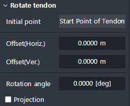
This enables the Rotation or Projection of the Tendon created by the coordinates of the Tendon Editor Table with respect to a specific axis.
Initial point : Select the point where the Rotation axis starts (passes by).
- Start Point of Tendon : The Tendon's Rotation axis passes the Start Point.
- Reference Point : The Rotation axis of the Tendon passes the reference point of the Tendon.Offset(Horiz.) : The position where the Initial Point that is Offset horizontally by the inputted value becomes the center of Rotation axis.
Offset(Ver.) : The position where the Initial Point that is offset vertically by the inputted value becomes the center of Rotation axis.
Rotation angle : Input the angle value that is to rotate around the Rotation axis.
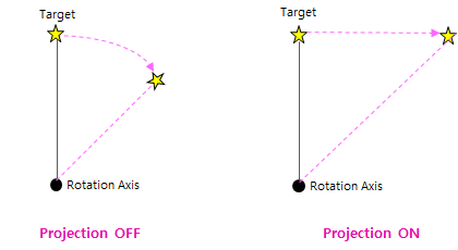
Projection : Rotation is practiced for the axis when it is Off, and projection is performed to the plane that had been rotated for the axis when it is On.
(In the case of Projection, it is mainly used to maintain the Offset-z value of the Target.)
Reference point
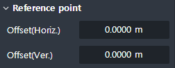
Moves the position of the Reference Point of the Tendon coordinate to directions toward the z-axis (Vertical) and x-axis(Horizontal), the distance just about the value that was inputted. The coordinate values inputted to the existing Tendon profile Table are not changed because they are relative values to the reference point.
Property Tab (Step 2)
Classification
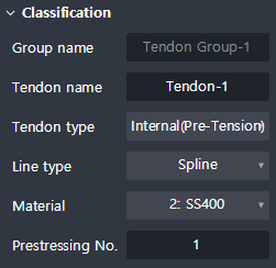
Set the properties of the Tendon.
Group name : Displays the name of the Tendon group to which the selected Tendon belongs.
Tendon name : Set the name of the Tendon.
Tendon type : Set the type of the Tendon. Three types are provided; the Pre-Tension /the Post-Tension / the External.
Line type : Sets alignment type of Tendon. Three types are available: Spline / Round / Polygonal.
Prestressing No. : Sets the prestressing number.
Tendon area
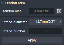
Set the tendon area directly.
Tendon area : Sets the value that was inputted by the user when the Use duct size option is off.
Duct size
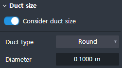
The tendon area is set automatically using the Duct setting.
Consider duct size : When the option is turned on, the Duct Area can be determined by entering the attribute value according to the Duct type.
Duct type : Two types are available; the Round and the Flat.
In the case of Round, as well as Diameter and Flat, you can select Duct by inputting Height and Breadth.
Anchorage Tab (Step 2)
Check On/Off
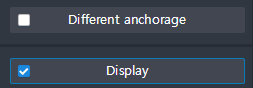
By checking different anchorage buttons, you can place different anchors at the beginning and the end of the Tendon.
If the Display button is checked ON, the Anchorage is expressed as a Graphic on the screen. If it is OFF, it is not displayed.
Anchorage list
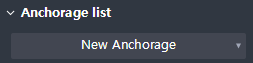
You can either define a New Anchorage or import a Tendon Anchorage that have been previously defined.
Classification
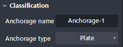
This sets the Name and Type of anchorage.
Anchorage name : Input the name of an anchorage.
Anchorage type : Select the type of anchorage. Three types(Plate / Flat / Dead End) are provided.
Shape
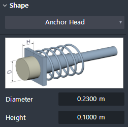
Determines the shape’s size on the anchorage.
Anchorage size is determined by inputting different Parameters for each Anchor type.
Tendon Editor Table
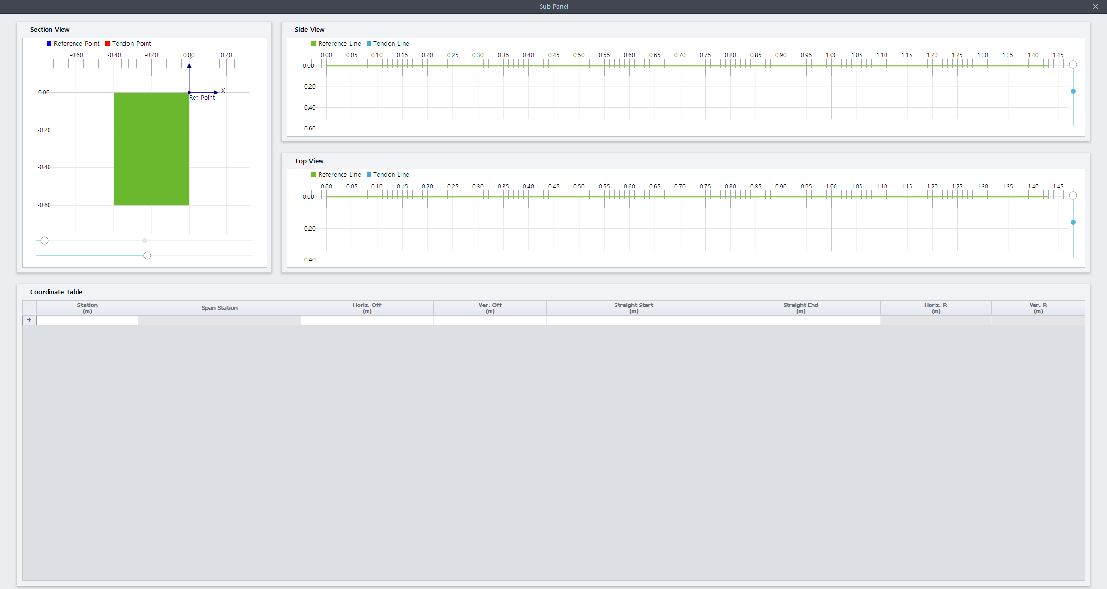
This is a table where you can enter / modify the coordinates of the actual tendon and view the view in three directions: Section / Side / Top.
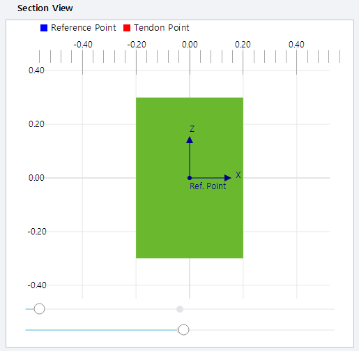
Section View
It is a View of Tendon section in direction of progress.
The location of the Tendon Point and Reference Point is shown on the section by red and blue dots, respectively.
The position of the upper dial at the bottom of Section View indicates the Station where the current section is located. (Left→Right)
The lower dial at the bottom of the Section View allows you to adjust the size of the Tendon name.
Side View
Displays the side View of the Tendon’s direction of progress.
Through the Add profile point > Point (Single point) function, you can mark a representative point of the Tendon.
Top View
It shows the top View of the Tendon’s direction of progress.
Through the Add profile point > Point (Single point) function, you can mark a representative point of the Tendon.
Coordinate Table
This is a table where the values of points occurred in Section / Side / Top View are displayed.
You can add points to the Section / Side / Top View by inputting values directly on the table.