Concrete > Column
Overview of Functions
Creates a concrete column member (1D).
Details of Functions
Create Tab
Column Option
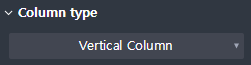
Sets the type (vertical / normal) of the concrete column member.
Vertical Column : Creates a vertical concrete column member.
General Column : Create a concrete column member of the general type.
Column height

Displayed when it is a Vertical Column.
Enter the height of the vertical type concrete column member.
Draw
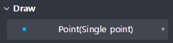
Provides Draw option for drawing columns.
Vertical Column
Point(Single Point) : Create a point by selecting one point.
Point(Center of points) : Create a point in the center of the entered sub-points.
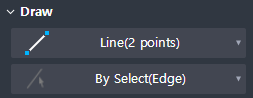
General Column
Line(2 points) : Select two points to create a line.
By Select(Edge) : Selects and creates lines on the plan drawing.
Preview level

Select the preview exposure level when the draw of the member is not complete.
Member With Solid : It shows both the center line of the member and its solid shape for the preview shape.
Member only : Shows only the center line of the member for the preview shape.
Property Tab > 1st sub tab
Classification
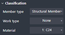
Sets the properties of a 1D column member.
Member type : Select an analysis type of an object for interface with midas Civil.
Work type : Select the work type.
Material : Select the material.
Group
Select a structure group.
Property Tab > 2nd sub tab
Tapered member option

Sets whether a cross section member is created.
Section
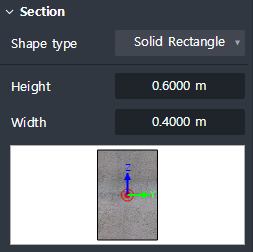
Set the type of section shape and enter section dimensions.
The types of sectional shapes provided are shown below.
Solid rectangle, Solid round, Octagon, Solid octagon, Track, Solid track, Half track
Local axis
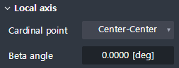
Sets the placement position and orientation of the section based on the center line of the member.
Cardinal point : Sets the position on the cross section corresponding to the center line of the member.
The section is positioned so that the location on the section you set matches the location of the center line of the member.
Beta angle : Input the rotation angle of the section.
The right-hand rule is applied to the Local x-axis of the member (start → end).
Additional offset
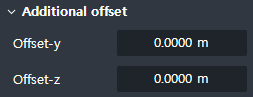
Additional offset distance from the Cardinal point position to the Local y, z direction is entered.
Offset-y : Enter the additional separation distance in the direction of the Local y.
Offset-z : Enter the additional separation distance in the direction of the Local z.
Shape variation
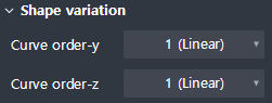
Displayed when Tapered member is checked ON
Define the connection geometry between the start and end section.
Curve order-y : Sets the curve order for the change of shape in the direction of the Local y-axis.
Curve order-z : Sets the curve order for the change of shape in the direction of the Local z-axis.
Property Tab > 3rd sub tab
Element type
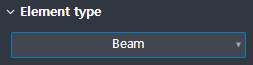
This sets the 1D element type.
Four types offered shown below.
Beam / Truss / Tension only / Compression only
Boundary condition
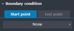
This sets the boundary condition at the beginning and end of the Geometry.