Draw (Rebar Draw)
Overview of Functions
CIM's rebar generation process provides an environment for modeling longitudinal profiles, transverse rebars, and stirrups in arbitrary planes and then arraying them in any direction.
At this time, the rebar drawing process in the rebar plane is more efficient in the 2D working environment, thus a separate rebar draw mode is provided.
This function explains the mode and the rebar draw function that is switched after selecting the plane to construct the rebar in the rebar draw function.
Details of Functions
Draw Tab
Rebar type
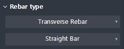
Select the type of rebar you want to build: Bar, Long Rebar, Stirrup.
Transverse rebar : Define the transverse rebar.
Longitudinal rebar : Defines the longitudinal rebar (in crossbar and subordinate relationships).
Stirrup : Defines the stirrup rebar.
Independent longitudinal rebar : Defines the longitudinal reinforcement bars.
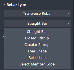
Rebar type > Transverse rebar > Rebar shape
Displayed when Rebar type is Transverse rebar
Choose how to construct the rebar.
The selection options change depending on the Rebar shape.
Straight Bar : Creates a straight bar.
Closed Stirrup : Creates closed bars with a cross-sectional shape relative to the rebar plane.
Circle Stirrup : Creates a circular crossbar . Applicable if the cross-sectional shape is circular.
One-Bending Shape : Creates one-bar bending bar at adjacent vertex locations.
Free Shape : Creates cross bars of user-defined shapes by providing Draw function of 'Line', 'Arc', 'Spline' and 'Select line'.
Select Line : Select a line drawn in advance to create a transverse rebar.
Select Member Edge : Select member edge on the Rebar plane to create a transverse rebar.
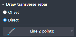
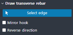
Rebar type > Transverse rebar >Straight rebar
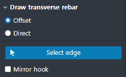
Create a straight rebar.
Offset : Creates transverse bars by selecting the edge of the section. The offset value is based on the value entered in the property window (Cover thickness> On plane).
- Select edge : Select the edge of the cross section.
- Mirror hook : Switches the hook start and end points set in the property.Direct : Create a crossbar using the Line draw (2 points draw) function.
Rebar type > Transverse rebar > Closed stirrup
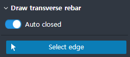
Creates closed bars with a cross-sectional shape relative to the rebar plane.
Auto closed (On) : Automatically creates closed transverse bars for the closed section of the part.
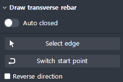
- Select edge : Select the edge of the cross section. The mouse point on the selected edge becomes the start and end positions.Auto closed (Off) : Creates closed transverse reinforcement for closed sections created by user-selected edges.
- Select edge : Select the edge of the cross section. If the selected edges (including the extension lines) form a closed section, a closed transverse bar can be created.
- Switch start point : Switch the start / end point position arbitrarily created at the intersection point of the edge.
- Reverse direction : Applies the rebar's position in the opposite direction relative to the edge.
Rebar type > Transverse rebar > Rebar shape > Circular stirrup
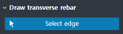
Create a circular crossbar. Applicable if the cross-sectional shape is circular.
Select edge : Select the edge of circular section.
Rebar type > Transverse rebar > Free shape
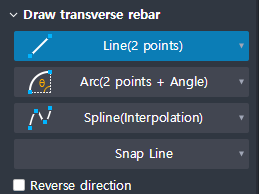
By creating Draw function of 'Line', 'Arc', 'Spline', and 'Snap line', you can create transverse bars of user defined shape.
Line(2 points) : Ÿ Create a line by entering two points.
Arc(2 points + Angle) : Creates an arc using two points and a center angle.
Arc(2 points + Radius) : Creates an arc using two points and a radius.
Arc(Three points) : Creates an arc using three points.
Arc(Tangent) : Creates an arc in the direction of contact with a 1D object (Line, Arc).
Spline(Interpolation) : Create a curve using a separate polynomial for each section by entering multiple points on the spline.
Spline(Control Point) : Creates a curve using a separate polynomial for each section by entering the spline's market point, control point, and endpoint.
Snap line : Creates a curve using polynomial by following the edge of the part with snap.
Sequence apply : Apply button for spline and snap line. You can extend it by selecting additional line option after clicking. ((Displayed at Spline and Snap line)
Reverse direction : Applies the rebar's position in the opposite direction relative to the edge.
Rebar type > Transverse rebar > Select line
Select the predrawn line to create the crossbar.
Select line : Select Line (sketch line, edge both). In the case of a series of lines, it creates a continuous rebar.
Mirror hook : Switches the hook start and end points set in the property.
Reverse direction : Applies the reinforcement's position in the reverse direction relative to the line.
Rebar type > Transverse rebar > Select member edge
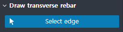
Select the member edge above the rebar plane to create the transverse rebar.
Select edge : Select the edge of member. When you select an edge, you must set the direction of the rebar along.
Reverse direction : Applies the rebar's position in the opposite direction relative to the edge.
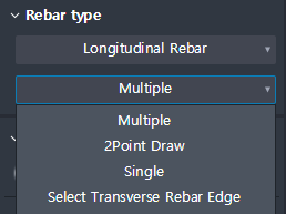
Rebar type > Longitudinal rebar > Rebar shape
Displayed when Rebar type is Longitudinal rebar
Choose how to draw the longitudinal rebar.
The selection options change depending on the Rebar shape.
Multiple : Select one part of the modeled crossbar to place the profile of the longitudinal rebar.
2 Points Draw : Click on two points on the modeled crossbar to place the profile of the longitudinal rebar.
Single : Click on a point within the modeled transverse rebar to place the rebar profile.
Select Transverse Rebar Edge : Select the required portion of the modeled crossbar to place the profile of the longitudinal rebar. You can select multiple cross bars to create longitudinal bars at once.
Draw Rebar > Longitudinal Rebar > Multiple
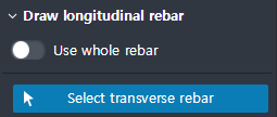
Select a part of the modeled crossbar to place the profile of the longitudinal rebar.
Rebar spacing applies to the Spacing value in the Properties window.
Use whole rebar : When activated, the profile of the longitudinal rebar is placed for the entire rebar.
Select transverse rebar : Select a part of the rebar.
Draw Rebar > Longitudinal Rebar > 2 Points Draw
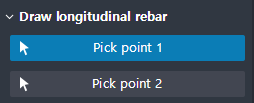
Click two points above the modeled crossbar to place the profile of the longitudinal rebar.
Rebar spacing applies to the Spacing value in the Properties window.
Select point 1 : Select the point where the profile of the longitudinal rebar begins on the rebar.
Select point 2 : Select the point where the profile of the longitudinal rebar ends on the rebar.
Draw Rebar > Longitudinal Rebar > Single
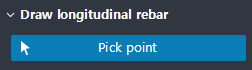
Click on a point within the modeled crossbar to place the rebar profile.
Select point : Select the point where the profile of the single longitudinal rebar will be placed on the rebar.
Draw Rebar > Longitudinal Rebar > Select Transverse Rebar Edge
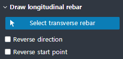
Select the required part of the modeled crossbar to place the profile of the longitudinal rebar. You can select multiple cross bars to create longitudinal bars at once.
Rebar spacing applies to the Spacing value in the Properties window.
Select transverse rebar : Select a part of the rebar . You can select it several times, and if you select the connected part, it will be recognized as one and create a longitudinal rebar profile.
Reverse direction : Applies the rebar's position in the opposite direction relative to the edge.
Reverse start point : Applies the start and end points of the longitudinal rebar profile in the opposite direction.
Draw Rebar > Stirrup
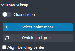
Create a stirrup reinforcing bar
Applicable to both cross and longitudinal rebars.
Closed rebar (On) : Produces a closed band bar.
Closed rebar (Off) : Produces non-closed band bars.
Select point type rebar : Select a point rebar (crossbar or longitudinal rebar) that depends on the band rebar.
Switch start point : Change the start and end positions of the band reinforcement.
Align bending center : When activated, the point reinforcing bar should be centered in the bending part of the band reinforcing bar.
Draw Rebar > Independent Longitudinal Rebar
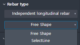
Select how the rebar will be constructed in the rebar and the independent rebar. Create virtual draw lines instead of flat bars to create dependent bars.
The selection options change depending on the Rebar shape.
Rebar type > Independent Longitudinal Rebar > Free shape
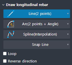
Draw line of 'Line', 'Arc', 'Spline', 'Snap line' to draw virtual Draw line to generate.
Line(2 points) : Create a line by entering two points.
Arc(2 points + Angle) : Creates an arc using two points and a center angle.
Arc(2 points + Radius) : Creates an arc using two points and a radius.
Arc(Three points) : Creates an arc using three points.
Arc(Tangent) : Creates an arc in the direction of contact with a 1D object (Line, Arc).
Spline(Interpolation) : Create a curve using a separate polynomial for each section by entering multiple points on the spline.
Spline(Control Point) : Creates a curve using a separate polynomial for each section by entering the spline's market point, control point, and endpoint.
Snap line : Creates a curve using polynomial by following the edge of the part with snap.
Sequence apply : Apply button for spline and snap line. You can extend it by selecting additional line option after clicking. (Displayed at Spline and Snap line)
Reverse direction : Applies the rebar's position in the opposite direction relative to the edge.
Rebar type > Independent Longitudinal Rebar > Select line
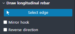
Create a rebar profile by selecting a pre drawn line as a virtual Draw line.
Select line : Select Line (sketch line, edge both). In the case of following lines, draw lines are recognized as one.
Mirror hook : Applies the start and end points of the longitudinal rebar profile in the opposite direction.
Reverse direction : Applies the reinforcement's position in the reverse direction relative to the line.
Property Tab > 1st sub tab
Classification
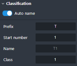
Define the name and the class of a rebar.
Auto name : If On, the window for entering the prefix and start number is activated.
Prefix : It is activated when Auto name is On, and sets a fixed value of auto-generated name.
Start number : It is activated when the setting of Auto name is On, and the name is automatically generated from the number designated as Start number.
(ex. Prefix: T and Start number: 5, the name is automatically assigned in the order of T5, T6, T7 .....)
Name : When Auto name is set to On, the name of the reinforcing bar currently entered is displayed and the user cannot edit it.
If you set Auto name to Off, you can enter your own name. (Duplicates allowed)
Class : Set the class of rebar. Depending on the class, you can easily group rebars into the same group.
Specification
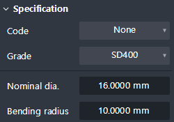
Set specifications such as the diameter and material of the rebar.
Code : Set Rebar Spec. Which set Bending Radius and Hook length by reinforcing bar diameter.
Grade : Select the grade of steel based on the selected criteria.
Diameter : Select the diameter of the rebar based on the selected criteria. It is activated only when the Code is selected. If Code is on None, setting is impossible.
Nominal dia. : Shows the nominal diameter of the rebar. If Code is None, it can be directly input.
Bending radius : Shows the bending radius that corresponds to the diameter of the rebar. Direct input is possible regardless of code.
Hook
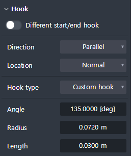
Set the Hook of rebar.
Different start/end hook : If activated, the Hook of the start side and the end side can be inputted differently. When activated, the Start point / End point tab are the buttons that are activated.
Direction : Sets the direction of the hook.
- Transverser Rebar : Parallel creates a hook in the direction parallel to the current plane, and Perpendicular creates a hook in the direction perpendicular to the plane to draw.
- Longitudinal Rebar : Parallel creates hook in the direction parallel to the transverse rebar, and Perpendicular creates a hook in the direction perpendicular to the transverse rebar.Location : Sets the location where the hook is created.
- Normal : The hooks are created inside the selected or drawn edge.
- Extended : The hooks are created outside the selected drawn edge.Hook type : Select the type of hook. Hook's radius and length are automatically entered according to the angle you specify.
- No hook : Does not make hooks.
- ±180° : Creates a hook to be a 180 ° hook.
- ±135° : Creates a hook to be a 135° hook.
- ±90° : Creates a hook to be a 90° hook.
- Custom hook : Create hook with user defined Angle, Radius, and Length information.Angle : You can check the angle value of the hook. (In the case of Custom hook setting, the hook angle can be set.)
Radius : You can check the Bending radius value of the Hook. (In the case of Custom hook setting, the Bending Radius of the Hook can be set.)
Length : You can check the length value (except for the Bending Radius) of the Hook. (In the case of Custom hook setting, the length of the Hook can be set.)
Cover thickness
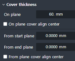
Sets Cover information from members.
Related rebar type : Transverse rebar, Stirrup, Spiral rebar, User group
On plane : Input the Cover value on the plane.
On plane cover align center : When activated, the On plane input value is the Cover value deriving from the center of the rebar.

From start plane : Input the Cover value that is farther from the start plane towards the rebar direction.
From end plane : Input the Cover value farther from the end plane towards the rebar direction.
From plane cover align center : When activated, the From start / end plane input value is the cover value from the center of the rebar.
Offset
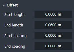
Enter the extension length of the reinforcing bar from the start and end points.
Related rebar type : Transverse rebar, Longitudinal rebar, Stirrup, Spiral rebar, User group
Start length : Enter the extension length at the start side of the rebar. If it is a (+) value, it is short. If it is a (-) value, it is long.
End length : Enter the extension length of the rebar end point. If it is a (+) value, it is short. If it is a (-) value, it is long.

Start spacing : When placing a Longitudinal Rebar, start by dropping the entered value from the time of user input.
End spacing : When placing a Longitudinal Rebar, start by dropping the entered value from the user input endpoint.
Start/End part
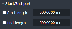
Set the length of the rebar at the start and end edges.
Related rebar type : Transverse rebar
Start length : Enter the length of the rebar for the start side edge. (When deactivated, you cannot enter a value and the rebar will be created for the selected edge.)
End length : Enter the length of the rebar for the end edge. (When deactivated, you cannot enter a value and the rebar will be created for the selected edge.)
Property Tab > 2nd sub tab
Splice
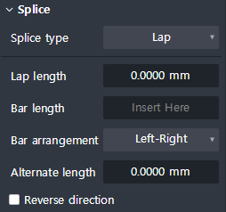
Sets the bars of the bars.
Splice type : Select the type of overlap. (Lap, Coupler, Welding)
Lap length : Enter the length of the Lap. (Apply when selecting Lap type. Coupler, Welding are not applied.)
Bar arrangement : Determines the type of array of overlapping joints. (Apply when selecting Lap type.)
Bar length : Enter the spacing of the overlaps. Overlaps are placed repeatedly as input values.
Alternate length : Arrange the layers in zigzag form. Enter the interval between 1cycle and 2cycle.
Reverse direction : When active, reverses the rebar's lap placement direction.
Variable rebar name
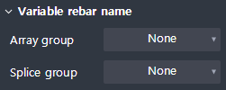
Sets the name of each bar in the rebar group.
Array group : Specifies a name for each rebar in the array.
-1, -2, -3, ……
A, -B, -C, ……
a -b, -c, ……Splice group : Specify a name for each rebar after setting the lap joints.