Steel > Beam
Overview of Functions
Create a steel beam member (1D).
Details of Functions
Create Tab
Draw
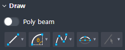
Creates a member by drawing the geometry of a steel beam member.
Line(2 points) : Select two points to create a line.
Arc(2 points + Angle): Creates an arc using two points and a central angle.
Arc(2 points + Radius) : Creates an arc using two points and a radius.
Arc(Three points) : Creates an arc using three points.
Arc(Tangent) : Creates an arc in the direction of contact with a 1D object (Line, Arc).
Spline(Interpolation) : Input a number of points on the spline and create a curve using a separate polynomial for each section.
Spline(Control Point) : Creates a curve using a separate polynomial for each section by inputting the spline's starting point, control point, and end point.
Semi-Ellipse : Creates a semi-ellipse by inputting the center of the ellipse, the point along the major axis, and the point along the minor axis.
By Select : Creates a concrete beam member by selecting a Line on the plan drawing.
Option
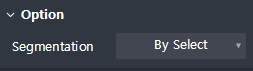
Select an option of whether a concrete beam is created as one object or several objects when several line objects are selected by ‘By Select’ function in ‘Draw'.
By Select : Create a continuous poly beam to the selected all line objects.
By Edge : Create discrete concrete beams for the selected each line object.
Preview level

Select the preview exposure level when the draw of the member is not complete.
Member With Solid : It shows both the centerline of the member and its solid shape for the preview shape.
Member only : It s hows only the centerline of the member for the preview shape.
Property Tab > 1st sub tab
Classification
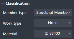
Sets the properties of a 1D beam member.
Member type : Select a type of analysis for interface with midas Civil.
Work type : Select the work type.
Material : Select the material.
Group
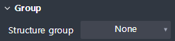
Select a structure group.
Property Tab > 2nd sub tab
Tapered member 옵션

Sets whether a cross-section member is created.
Section
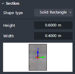
Set the type of section shape and enter section dimensions.
The types of sectional shapes provided are shown below.
Solid rectangle, Solid round, Octagon, Solid octagon, Track, Solid track, Half track
Local axis
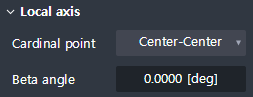
Sets the placement position and orientation of the section relative to the centerline(Geometry) of the member.
Cardinal point : Set the position on the section corresponding to the centerline of the member.
The section is positioned so that the placement of the section you have set matches the location of the centerline of the member.
Beta angle : Enter the rotation angle of the section.
The right-hand rule is applied to the Local x-axis of the member (start → end).
Additional offset
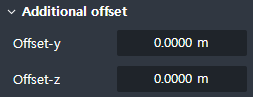
Additional distance from the cardinal point position to the local y, z direction is necessary to be entered.
Offset-y : Enter the additional separation distance in the direction of the Local y.
Offset-z : Enter the additional separation distance in the direction of the Local z.
Shape variation
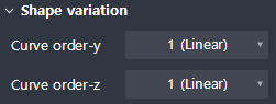
Displayed when Tapered member is checked ON
Define the connection geometry between the start and end section.
Curve order-y : Sets the curve order for the change of shape in the direction of the Local y-axis.
Curve order-z : Sets the curve order for the change of shape in the direction of the Local z-axis.
Property Tab > 3rd sub tab
Element type
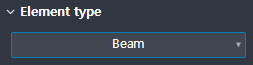
This sets the 1D element type.
Four types are available.
Beam / Truss / Tension only / Compression only
Boundary condition
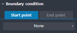
This sets the boundary condition at the beginning and the end of the geometry.