Layout > Create-Edit
Overview of Functions
Define three-dimensional paths (Layout) for modeling infrastructures such as roads, bridges, and tunnels.
Defines the alignment and profile respectively and defines the segments based on the alignment.
The modeled layout can be used to assign ULT.
Details of Functions
Create & Edit Tab
Layout list
This function defines a new path or load information on an existing layout.
Classification
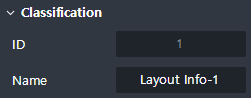
This function defines ID and Name of Layout.
ID: Define the identification number of a layout.
Name: Define the name of a layout.
Location
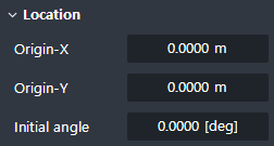
This function sets the origin coordinate to place the layout on the model view.
Origin-X: Enter the x-coordinate of the starting point in the alignment.
Origin-Y: Enter the y-coordinate of the starting point in the alignment.
Initial angle: Enter the initial angle in the x-y plane to define the direction of the alignment.
Grid Setting
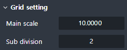
This function sets the grid of the layout that is displayed on the table.
Main scale: Defines the interval of major gridlines(Default: 10m).
Sub division: Defines the number of divisions between major gridlines(Default: 2).
Layout Editor
Alignment
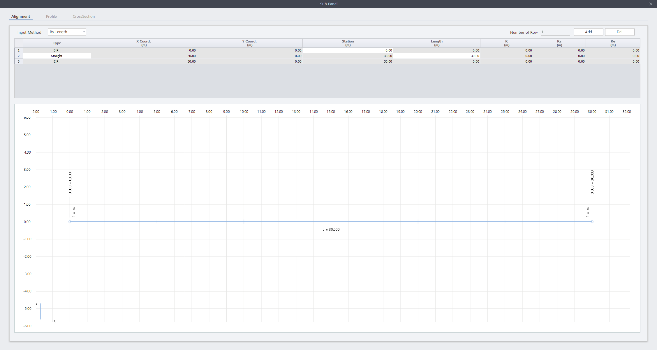
This table defines an alignment of a path. The picture at the bottom of the table is updated along with the entered value.
Input Method
By Length: Define an alignment using the length of each section.
By X, Y: Define an alignment using x, y coordinate values (X, Y Coord.) of each section.
By DWG Data: Define an alignment using a 2D CAD file.
Number of Row / Add / Del
Number of Row: Define the number of rows to add at once.
Add: Add a row.
Del: Delete a row.
Table Composition
Type: Select a type of alignment.
- B.P. & E.P.: The beginning point and the end point of the alignment.
- Straight: Define a straight region at the line between a segment end point and the preceding point.
- Arc: Define a curved region at the line between a segment end point and the preceding point.
- Clothoid: Define a clothoid region at the line between a segment end point and the preceding point.X Coord. / Y Coord.: Enter values into x and y coordinate of the alignment section. For the 'Straight' type section, Input in the coordinates of the starting point. For the 'Arc' and 'Clothoid' types, Input in the intersection coordinates of the circumference line.
Station: Indicate the station with respect to the segment end point on the alignment. The station value of 'BP' can be Inputted directly, while the remaining points are automatically calculated by the length of each section.
Length: Input the length between a segment end point and a preceding point on the alignment.
R: This column is activated when the type of alignment is 'Arc'. Enter the radius value of the arc.
Rs / Re: This column is activated when the type of alignment is 'Clothoid'. Enter the radius value of the clothoid at the beginning and end.
Profile
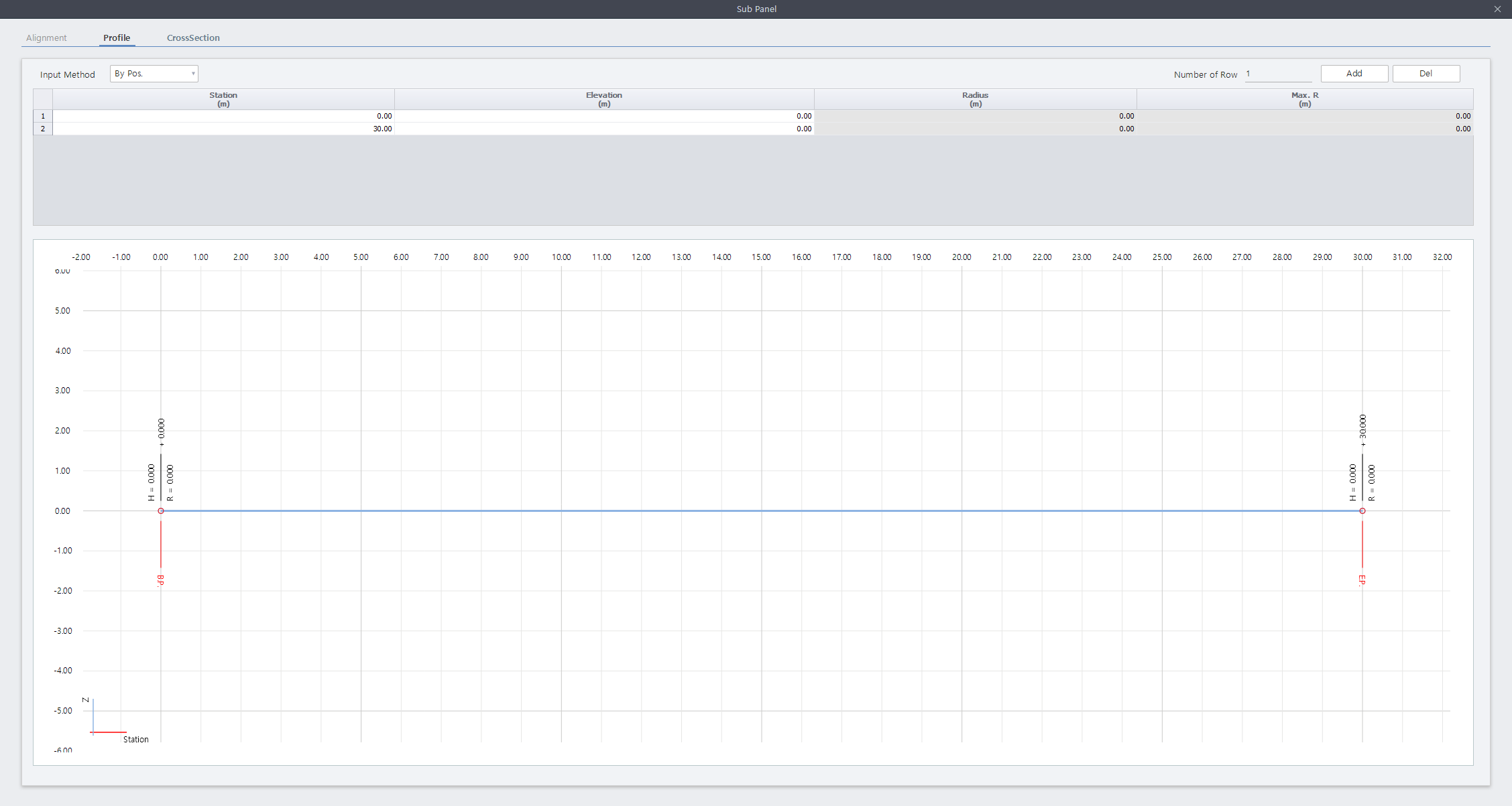
This table defines the profile of a path. The picture at the bottom of the table is updated along with the entered value.
Input Method
By Pos.: Define a profile by applying relative elevation from the start of a path.
Number of Row / Add / Del
Number of Row: Define the number of rows to add at once.
Add: Add a row.
Del: Delete a row.
Table Composition
Station: Enter the station with respect to the profile. To facilitate practical work, inputting smaller or larger value than the station of E.P. & B.P. is available.
Elevation: Enter the elevation at each station on the profile. Both negative and positive values can be Inputted.
Radius: Enter the radius value at the station point on the profile. It is available to input when another station exists at front and back.
Max. R: The maximum radius value that can be Inputted in as 'Radius' value. The maximum radius value is automatically calculated by using the “curve formula for tangent distance”, spacing, as well as the elevation difference.
Cross Section
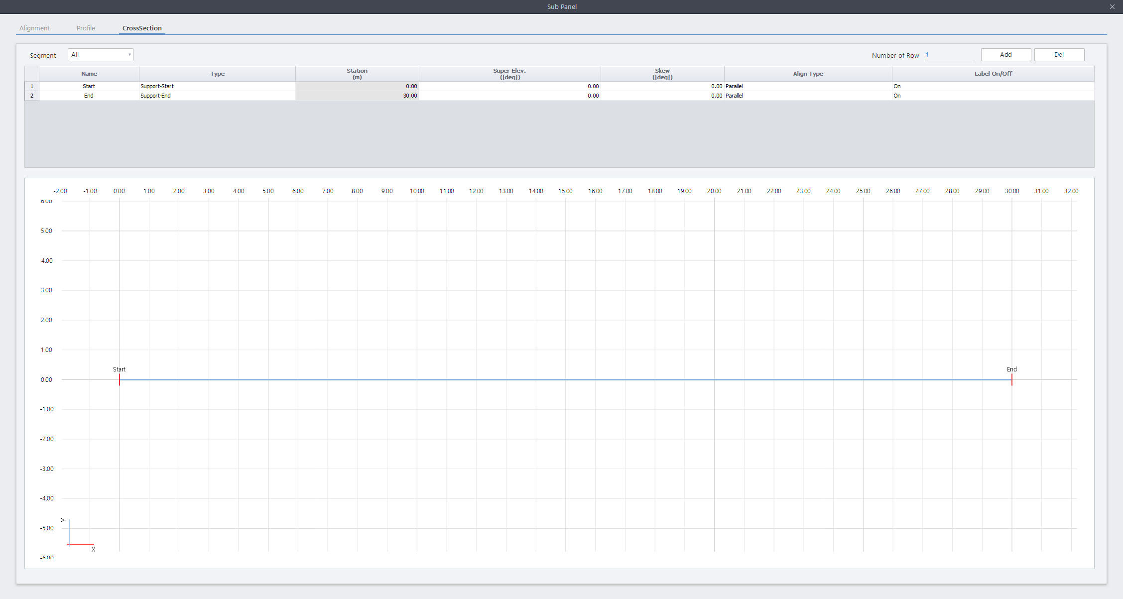
This table sets the position and a type of section in a path.
Number of Row / Add / Del
Number of Row: Define the number of rows to add at once.
Add: Add a row.
Del: Delete a row.
Table Composition
Name: Enter the name of the segment point.
Type: Specify the type of the segment point. 'Support', 'Support-Start', 'Support-End', 'Construction Joint', 'Cable Connection Point' and 'Dividing Point' types are given.
Station: Enter the station of the segment point.
Super Elev.: Enter the superelevation of the segment point.
Skew: Enter the skew of the segment point.
Align type
- Tangential: Specify that the Profile plane direction at the Segment Point is perpendicular to the alignment layout.
- Parallel: Specify that the Profile plane direction at the Segment Point is parallel to the global z-axis.Label On/Off: Specify whether to activate the Label of Segment Point.