Rebar > Array
Overview of Functions
After defining the 'Rebar plane' at any position and direction for the selected objects (1D, 2D), create rebars and crossbars.
The modeling process for rebars is as follows:
Step 1. Use the 'Draw rebar' function to select the target object and define the rebar plane.
Step 2. Use Rebar Draw Mode and draw a crossbar profile and a rebar profile.
Step 3. The rebar profile is created into a group of crossbars with the Array function, and the rebars are arranged in respect to the target object.
Details of Functions
Array Tab
Type
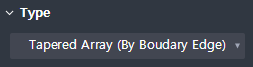
Choose how to arrange the rebars.
We offer three types of rebar arrangement methods: Tapered array (By boundary edge), Array along path, and the Sweep array type.
Tapered Array (By Boundary Edge) : Specifies the shape (Boundary edge) of the object as the criteria of rebar arrangement. Reflects the changes in rebar shapes based on the changes in the section developed in the longitudinal direction of the cross sections.
Array Along Path : Specifies the criteria of bar arrangement as ‘its path’. This only takes into account the changes that have been made on the sections of the rebar plane, and does not reflect changes in section such as cross-sectional changes, which bases on longitudinal direction.
Sweep Array : This allows to draw rebars, which are susceptible to change in its length since they are composed of arbitrarily designated Paths made of Vertex Points. These points, which are composites of Transverse bars, do not put the shape of members into consideration.
Select rebar

Select the Transverse rebar or Longitudinal rebar profile that you would like to arrange.
Select additional member

If the rebar of your choice has an Additional target to array other than the Target member that is subordinate to it, select the additional member.
Additional member is valid only when it is in a continuous with the Target member.
Define end plane
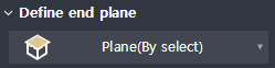
Define the end plane in which the rebars will be arranged.
The reinforcing bars will be arranged through an already defined Path, up to the end plane.
As a plane definition method, we provide By select, Select rebar plane, 3 points, By offset, Curve normal.
If you define a plane, the screen switches to the Drawing mode, used for drawing bars.
By select : Select a plane by selecting a face on the plan drawing.
Select rebar plane: If you select the drawn Rebar, it defines the plane where the Rebar is drawn on.
3 Points : Marking 3 dots on the plan drawing, a Plane is defined as the figure that is formed by the three dots that have been drawn.
By offset : Define Plane as the position offset by selecting an existing Face on the plan drawing.
Curve normal: Define a vertical plane as a Plane, by selecting a point on the line on the plan drawing.
Reference path of spacing
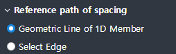
Define the array path of the rebars.
The path you have selected must be continuous and must pass through the starting plane and the end plane, where the bars will be arranged.
Geometric Line of 1D Member : Specifies the centerline of the selected member as the array path.
Select Edge : Selects line objects to specify as array paths.
Longitudinal rebar option

Sets whether the change in longitudinal cross-sectional shape of the member should be considered when the arrangement of longitudinal bars is planned.
Follow Transverse: Longitudinal bars are created along the array of Transverse bars.
Follow Path: Longitudinal bars are created along the Array Path.
Define point path
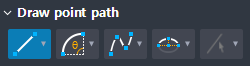
Displayed when Type > Sweep Array
Defines the Path of each Vertex Point that constitutes the rebar (cross bar). If at least one of the Vertex points does not specify a path, the rebars are not arranged.
As for the methods of defining paths, Line (2 points), Arc, Spline, Semi-ellipse, By select (edge) are provided.
Delect selected objects : This option deletes the paths of selected Vertex points which were chosen through the By select (edge) method, after the rebar arrangement has been made.
Property Tab
spacing
This property sets the spaces when rebars are arranged. Transverse bars and Stirrup bars are arranged using this function.
Related rebars: Transverse rebar, Stirrup Spacing options with Adjustable spacing, By number, Limit Max. Spacing, Pattern spacing and User defined are provided.
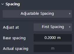
Adjustable Spacing
After arranging by the space value that the user has aimed, the rebar that is left is added to the remaining spaces. Depending on the option, it adjusts the rebar spaces for the starting point, end point, and midpoints.
- Adjust at
① First spacing : After arranging the rebar by Base Spacing Values, adjust the remaining value at the first rebar space.
② Last spacing : After arranging by Base Spacing values, adjust the remaining value at the last rebar spaces.
③ First/Last spacing : After arranging by Base Spacing values, adjust the remaining value after dividing the remaining values into two groups, that is, putting them in the first and last rebar spaces.
④ Middle spacing : After arranging by Base Spacing values, adjust the remaining value at the spaces between middle reinforcing bars (in case of odd numbers, adjustment is to be made close to the starting point).
- Base spacing : Set the Target Spacing Value. Arrange the values according to their values following the Array path.by Number
Arranges the number inputted equally, regardless of spacing.
- Number of rebar : Input the number of rebars that the user wants to arrange.Limit Max.spacing
Arrange by spaces that does not exceed the values that have been inputted.
- Max. spacing : Input the maximum number for spacing. Arranges rebars without allowing a gap greater than the gap inputted.Pattern spacing
Arranges only as much as you have inputted, and no additional arrays are to be added.
- Spacing : The spacing value entered here is arranged and spacing smaller than the spacing will not be arranged.User defined
Type in the space you want.
- Spacing : Input the space you want, at your discretion. (ex. 3 @ 200, 400, 5 @ 150)Actual spacing : Displays the actual spacing arranged. (Displayed only in the property window of the completed rebar.)