By Plane
Overview of Functions
Define a view plane for generating drawing information for cross sections of arbitrary position. It generates drawing information based on the location and extent of the reference planes and updates them to MIDAS Drafter.
Details of Functions
Create Tab
On/Off Option

When checked, MIDAS Drafter is launched and drawing information is updated from the created view section information.
Classification
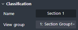
Defines the basic information of the view plane to be created by the cutting plane.
Name : Enter the section name of the view plane to be created.
View group : Specify the Group of the view plane. Select the section group defined in View > Group
Define plane

Define the view plane.
By Select : Select a face on the plan drawing to define the vertical plane.
3 Points : Plane is defined by consisting of 3 points by taking 3 points on the plan drawing.
Curve Normal : Defines a vertical plane as a plane by selecting a point on the line on the plan drawing.
By Offset : By selecting an existing face on the plan drawing and define the plane at an offset position.
Select Rebar Plane : Select the drawn Rebar to define the plane where the Rebar is drawn.
View depth
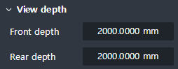
Defines the forward and backward field of view of the view plane.
Front and rear view ranges means the front and rear ranges to generate drawing information from the view plane.
Front depth : Enter the front view thickness (+ y direction) of the defined view plane.
Rear depth : Enter the thickness of the rear view range (-y direction) of the defined view plane.
Cutting area
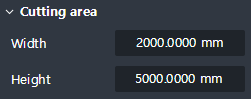
Define the width and height of the view plane.
Width : Enter the width (x direction) of the view plane.
Height : Enter the height of the view plane (z direction).