Concrete > Wall
Overview of Functions
Create a concrete wall member (2D).
Details of Functions
Create Tab
Wall type

Sets the type (vertical / general) of the concrete wall member.
Vertical Wall : Creates a vertical wall member of the vertical type.
General Wall : Creates a concrete wall member of the general type.
Wall height

Displayed only when it is a Vertical Wall
Enter the height of the concrete wall member that is a vertical type.
Draw
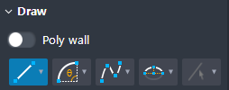
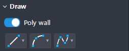
You can draw shapes with the Draw function.
Vertical Wall
Line(2 points) : Select two points to create a line.
Arc(2 points + Angle) : Creates an arc using two points and a center angle.
Arc(2 points + Radius) : Creates an arc using two points and a radius.
Arc(Three points) : Creates an arc using three points.
Arc(Tangent) : Creates an arc in the direction of contact with a 1D object (Line, Arc).
Spline(Interpolation) : Input a number of points on the spline and create a curve using a separate polynomial for each section.
Spline(Control Point) : Creates a curve using a separate polynomial for each section by inputting the spline's starting point, control point, and end point.
Semi-Ellipse : Creates a semi-ellipse by inputting the center of the ellipse, the point along the major axis, and the point along the minor axis.
By Select(Edge) : Select the edge directly.
General Wall
Point(Single Point) : Create a point by selecting one point.
Point(Center of points) : Create a point in the center of the inputted sub-points.
Line(2 points) : Inputs two points to create a line.
Arc(2 points + Angle) : Creates an arc using two points and a center angle.
Arc(2 points + Radius) : Creates an arc using two points and a radius.
Arc(Three points) : Creates an arc using three points.
Arc(Tangent) : Creates an arc in the direction of contact with a 1D object (Line, Arc).
Spline(Interpolation) : Input a number of points on the spline and create a curve using a separate polynomial for each section.
Spline(Control Point) : Creates a curve using a separate polynomial for each section by inputting the spline's starting point, control point, and end point.
Semi-Ellipse : Creates a semi-ellipse by inputting the center of the ellipse, the point along the major axis, and the point along the minor axis.
Rectangle(Center point 1) : Creates a rectangle by inputting the center and one vertex of the rectangle.
Rectangle(Center point 2) : Creates a rectangle by inputting the center of the rectangle and the two corner center points.
Rectangle(Corner two points) : Creates a rectangle by inputting two points diagonally.
Rectangle(Corner three points) : Creates a rectangle by inputting three vertices.
Circle(Ceneter point) : Create a circle by inputting a point on the center and perimeter of the circle.
Circle(Three points) : Create a circle by inputting three points on the perimeter of the circle.
Ellipse(Center point) : Create a circle by inputting the center of the ellipse, a point in the major axis direction, and a point on the perimeter.
Ellipse(Corner point) : Creates an ellipse by inputting two points along the major axis of the ellipse and a point on the perimeter.
Track(Center Point) : Create a track by inputting two points on the track's center and perimeter.
Track(Corner Point) : Create a track by inputting two points on the center and perimeter.
Polygon(Circumscribed) : Creates a polygon tangent to a circumscribed circle.
Polygon(Inscribed) : Creates a polygon tangent to an inscribed circle.
By Select(Edge) : Select the edge directly.
By Select(Plane) : Select the face directly.
Option

Displayed only when it is a General Wall
When checked on, the wall is created with reference to the closed inner hole.
Preview level

Select the preview exposure level when the draw of the member is not complete.
Member With Solid : This shows both the centerline of the Member as well as its Solid shape for the preview shape.
Member only : This shows only the centerline of the Member for the preview shape.
Property Tab > 1st sub tab
Classification
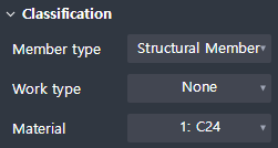
Set the properties of the 2D wall member.
Member type : Select a type of analysis for interface with midas Civil.
Work type : Select the work type.
Material : Select the material.
Group

Select a structure group.
Property Tab > 2nd sub tab
Thickness

Enter the thickness.
Cardinal point

Sets where to apply the thickness that accords with the members’ Center Plane (Geometry).
Additional offset
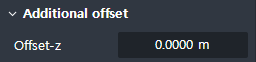
Enter the additional separation distance from the Cardinal point position to the local z direction of the section.