General > Steel
Overview of Functions
Creates a general member with the properties of a steel.
General member is a function used for modeling atypical shapes. It is different from the modeling method of basic members (EX. Concrete Beam) as explained below.
General member
After creating a section (= cross section), the shape is created by extruding the section (Extrude) or by connecting the sections (Loft).Basic member
With the properties of the section (type, dimension, etc.) already set in the property window, the shape is created by drawing the center line directly.
Details of Functions
Create Tab > 1st sub tab
Check on/off option

When the option is checked on, the different cross section can be selected at Start / End of the member
User section list

A list of the user sections available in the current mode is displayed.
Select the name of the section you want and a preview of that section appears.
Assign section
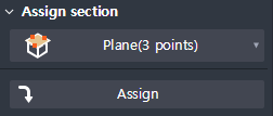
This is the function to set the plan where the user section will be entered.
Set the plan by a three-point input process in the following order: Origin Point> X-Axis> Y-Axis.
Press the Assign button and it will appear on the screen.
Origin point
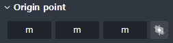
The coordinates of the origin set by the Assign Section Function are displayed.
You can modify the origin coordinates by entering the number directly or selecting a point.
Local axis
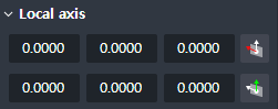
The direction vector of the Local axis set by the Assign Section Function is displayed.
You can modify the coordinates by entering the number directly or selecting a point.
Generate member
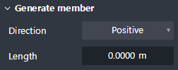
Set the Section’s direction of extruding and enter its distance of extraction.
Direction: You can change the direction of extrusion.
Length: Determines the distance of extrusion.
Create Tab > 2nd sub tab
Define path
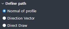
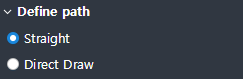
Define the Section’s path of extraction.
Displayed when Tapered member check is OFF
Normal of section: Extrude in the normal direction of the Section Plane.
Direction vector : Extrude in the direction of the vector placed.
Direct draw : Draw the path of extrusion directly.
Displayed when Tapered member is checked ON
Straight : Connects the Start and End profiles in a straight line.
Direct draw : Draws the connection path directly.
Cardinal point
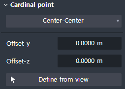
Sets the center-line position of the member.
Cardinal point : Sets the centerline position based on the Bounding box of the profile.
Offset-y : Enter the additional distance from the present Cardinal point to the direction of the Local-y axis of the profile.
Offset-z : Enter the additional distance from the present Cardinal point to the direction of the Local-z axis of the profile.
Define from view : When clicking on the button, you can set the Cardinal point by clicking anywhere on the profile plan.
Create Tab > 3rd sub tab
Auto matching rule

Set the Automatic Vertex Matching Method between the Start and End profiles.
Quadrant connection : After matching the reference, vertices of each quadrant, vertices are sequentially matched according to the Loop Sequence of the profile in the direction of 'up → down' and 'left → right'.
Quadrant half area : After matching the reference vertices of each quadrant, vertices are sequentially matched within each quadrant, according to the Loop Sequence of the profile.
Loop sequence : After matching the reference vertices of the first quadrant , match the vertices sequentially according to the Loop Sequence of the profile. However, if the number of vertices in the start and end profiles does not match, the Quadrant Half Area Method will automatically be applied.

Since the three methods mentioned above are automatic matching methods based on program rules, the desired vertex matching results that the user might have pursued is not guaranteed.
Therefore, if it is possible to match the number of vertices in the Start profile and End profile through CAD work, then the Loop Sequence Method is recommendable.
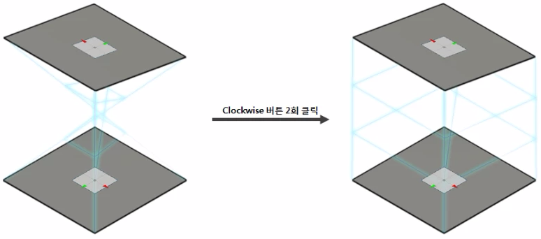
Rotate quadrant of end section
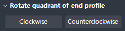
Displayed when Tapered member is checked ON
Displayed when the Auto Matching Rule is a Quadrant connection, or a Quadrant half area
Rotates the End profile of the Quadrant order.
Clockwise : Rotates the Quadrant order of the End profile clockwise.
Counterclockwise : Rotates the Quadrant order of the End profile counterclockwise.
The orders concerned with the Quadrants of the Start and End profiles may turn out different from what the user has expected due to a program’s internal rules or layout behaviors of General Sections.
The Rotate quadrant of end section allows you to adjust the order of the quadrants, should situation like these occur.
Create Tab > 4th sub tab
Shape variation
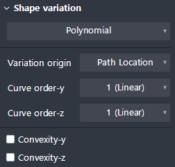
Displayed when Tapered member is checked ON.
Defines the connection geometry between matched Vertices.
Variation origin : Sets the reference point on the profile to determine whether the curve can be connected.
Vertex Sets that have the same distance from the Variation origin are always connected in a straight line regardless of the settings of the Shape variation.
For example, the figure below shows a member created by setting a Variation origin differently and the Curve order to '2 (Parabolic)' for the same profile.
Looking at the connection shape of the top Vertex of the Start / End profile, the left member has a different distance from the center-center, so the curve connection is applied and the right member has the same distance from the Center-Top (0) than the Curve order setting. Thus, you can see that a straight line connection is applied irrespective of the Curve order setting.

(Polynomial)
Curve order-y : Sets the order of the curve with respect to the direction of the local y-axis.
Curve order-z : Sets the order of the curve with respect to the direction of the local z axis.
(Arc)
Radius-y : Enter the radius of curve towards direction of Local y-axis.
Radius-z : Enter the radius of curve towards direction of Local z-axis.
Convexity-y : Check when applying curve that changes convexly about the direction of Local y-axis.
Convexity-z : Check when applying curve that changes convexly about the direction of Local z-axis.
The rules for applying concave or convex curved shapes are shown below.
- Concave: Tangential curve shape is applied at the position of the Vertex that is close to the Variation origin.
- Convex: Tangential curve shape is applied at the position of the Vertex which is far from the Variation origin.

Option
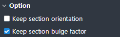
Sets the options that change Section according to the Paths.
Keep section orientation : When checked On, the direction of the existing Section is maintained regardless of the path bent while proceeding.
Keep section bulge factor : When checked on, it maintains Section extrusion rate in accordance with object's length change.
Property Tab > 1st sub tab
Classification
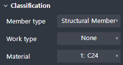
This sets the properties of General Member.
Object type : This indicates the type of object.
Member type : You can select the type of member.
Work type : You can select the type of work.
Material : You can choose the material.
Group

Select a structure group.
Property Tab > 2nd sub tab
Element type
This sets the 1D element types.
Four types offered below are available.
Beam / Truss / Tension only / Compression only
Boundary condition
This sets the boundary condition at the beginning and end of the Geometry.