1D Member
Overview of Functions
Description of information for properties that is popped-up by selecting 1D member.
Details of Functions
Property Tab > 1st sub tab
Classification
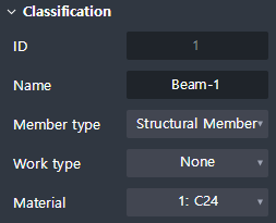
Check or edit the classification of an object.
ID : Show the identification number of an object.
Name : Show the name of an object.
Member type : Show the member type of an object.
Work type : Show the work type of an object.
Material : Show the material of an object.
Group
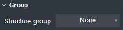
Check or edit the structure group.
Structural group : Show the name of structure group that an object is assigned.
Geometry
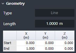
Check or edit the geometry information of an object.
Line
Type : Show the type of geometry.
Length : Show the length of a line object.
Table : Show the coordinate of geometry based on GCS.
- Start : The coordinate at the beginning of a line object.
- End : The coordinate at the end of a line object.
Arc
Type : Show the type of geometry.
Angle : Show the central angle of an arc object.
Radius : Show the radius of an arc object.
Circumference : Show the circumference of an arc object.
Fix vertex location : Check on to fix vertexes at both ends of an arc object when the central angle or radius is modified.
Table : Show the coordinate of geometry based on GCS.
- Center : The coordinate at the center of an arc object.
- Start : The coordinate at the beginning of an arc object.
- End : The coordinate at the end of an arc object.
- Reference axis : Vector value from Arc's center point in the view direction.
- Normal : Vector value from the center point of Arc in the direction normal to the arc plane.
Spline
Type : Show the type of geometry.
Length : Show the length of the spline object.
Point type : Show the type of geometry.
Table : Show the coordinate of geometry based on GCS.
(In case that point type is 'Control point'.)
- CP# : The coordinate of the control point.
(In case that point type is 'Vertex'.)
- Start : The coordinate at the beginning of a spline object.
- End : The coordinate at the end of a spline object.
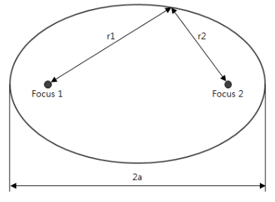
Elliptic arc
Type : Show the type of geometry.
Angle : Show the central angle of an elliptic arc.
Major radius : Show the major axis radius of the elliptic arc.
Minor radius : Show the minor axis radius of the elliptic arc.
Circumference : Show the circumference of an elliptic arc object.
Table : Show the coordinate of geometry based on GCS.
- Center : The coordinate at the center of the elliptic arc.
- Start : The coordinate at the beginning of the elliptic arc.
- End : The coordinate at the end of the elliptic arc.
- Major axis : Vector value from the center point of the elliptic arc to the start direction.
- Normal : Vector value from the center of the elliptic arc in one direction normal to the elliptic arc plane.
- Focus 1 : First fixed point for the calculation of elliptic arc.
- Focus 2 : Second fixed point for the calculation of elliptic arc.
Solid
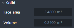
Show the final geometry of a solid.
Face area : Show the summation value for the face area of the solid. 솔리드 면의 면적 합계가 나타납니다.
Volume : Show the volume of the solid.
Field

The field is activated when the work type is defined in the object.
Set Field and Tag according to Work type.
Number of field : Set the number of fields.
Graphic
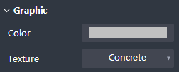
View and edit graphical information of objects.
Color : Set the color.
Texture : Sets the material that is mapped to the face.
Property Tab > 2nd sub tab
On/Off Option

Sets whether a section member is created.
Check Off :Create a section member.
Check On : Create a section member.
Section
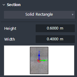
Set the type of section geometry and enter the section dimensions.
Concrete member
- Solid rectangle, Solid round, Octagon, Solid octagon, Track, Solid track, Half trackSteel member
- Angle, Channel, H-Section, T-Section, Box, Pipe, Solid round
Local axis
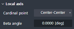
Set the placement position and orientation of the section relative to the centerline of the part.
Cardinal point : Set the location on the section that corresponds to the centerline of the part. The section is positioned so that the location on the section you set matches the location of the centerline of the part.
Beta angle : Enter the angle of rotation of the section. The right-hand rule is applied around the local x-axis of the part (start → end).
Additional offset
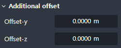
Enter an additional separation distance from the cardinal point position in the local y, z direction of the cross section.
Offset-y : Local Enter an additional separation distance in the y direction.
Offset-z : Enter an additional separation distance in the Local z direction.
Shape variation
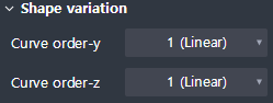
The shape variation is activated when the tapered member option is turned on.
Define the connection geometry between the start and end section.
Curve order-y : Local Set curve order for shape change in y direction.
Curve order-z : Local Sets curve order for shape change in z direction.
Property Tab > 3rd sub tab
Element type
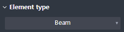
Sets the element type to interlock with midasCivil.
Beam : To the beam element.
Truss : Interlock with the truss element.
Tension Only : Interlock with tension only elements.
Compression Only : Works with compression-only elements.
Boundary condition
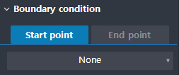
Release can be applied to each start / end node.
Construction
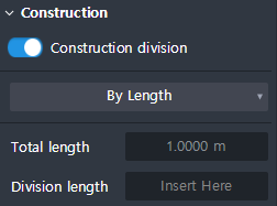
The element is divided and linked according to the input of the construction division position.
By length : Enter the length of the construction segment as the length.
- Total length : The length of the entire 1D element is displayed.
- Division length : Enter the length of the construction split location.By Ratio : Enter the construction segment as a percentage.
- Division ratio : Enter the percentage of the total length of the construction split location.